How I Built a Motion-Activated Greeter Bot
December 5, 2025
 The motion-activated greeter bot
Since I got my 3D printer last year, I've been wanting to build an entire device, from the electronics to the software to the physical enclosure. But I didn't have much experience in schematic design or PCB layout, so I've spent the past few months learning and refreshing my EE knowledge. I've been reading The Art of Electronics, watching YouTube videos, breadboarding, and even designed a few PCBs with KiCad, which I hand-soldered myself. Once I felt reasonably comfortable, I decided I was ready to take it up a notch.
I work at a startup, and have 3D printed quite a few plant pots, keychains, and coasters for the office. I often extrude our company logo from the surface of these objects, so they feel like our own. So I thought it would be fun if, as a next step, I put our logo in motion.
My idea was simple, and inspired by the motion-activated lights that are often in office buildings, bathrooms, and smart home setups. I wanted a device that would detect motion and wave a hand with the company logo centered in the palm. I wanted to place it near our elevators, so it would wave to you every time you entered or left the office.
The only input would be a PIR sensor, which would trigger when motion was detected. And since a hand only needs to turn about 120 degrees to wave, a single servo could serve as the output.
PIR Sensor
A PIR (passive infrared) sensor detects motion by leveraging the pyroelectric effect. When any heat-producing body moves in range of the sensor, the heat differential across the sensor's internal crystals causes a very small voltage to be produced. This voltage is amplified to become the 3.3V signal that is fed into the microcontroller, PIR_IN. When this signal goes high, it triggers the hand to wave.
Servo
I chose the MG995 servo as the mechanism to wave the hand. A micro servo could've definitely worked, even with its lower torque (1 kg x cm), as the hand only weighs about 10 grams.
The rotational position of the servo is controlled by a pulse-width modulated (PWM) signal. By incrementally increasing and then decreasing the duty cycle of the PWM signal, you can rotate the servo back and forth, producing the waving effect.
But how does triggering the PIR sensor result in a modulating PWM signal? That's where the microcontroller comes in. I chose the ATMEGA328P-PU because it's compatible with the Arduino IDE, so it'd be easy to flash and troubleshoot as my first microcontroller-based PCB project. The microcontroller's job is easy; it only has to check if PIR_IN is high, and if so, start modulating the PWM signal.
The Code
cpp#include <Servo.h>

const int PirPin = 2;
const int ServoPin = 9;
const int MotionDelay = 5000;
Servo MyServo;

#ifdef LOG_ON
  #define LOG(fmt, ...)  Serial.println((fmt "\n"), ##__VA_ARGS__)
#else
  #define LOG(fmt, ...)  do {} while(0)
#endif

void setup() {
  #ifdef LOG_ON
  Serial.begin(9600);
  #endif
  pinMode(PirPin, INPUT);
  MyServo.attach(ServoPin);
  MyServo.write(0); // Center position
  MyServo.detach();
  LOG("PIR Servo Motion System Ready");
}

void loop() {
  int pirState = digitalRead(PirPin);
  LOG("Loop start");

  if (pirState == HIGH) {
    LOG("Motion detected!");

    MyServo.attach(ServoPin);
    sweepServoNTimes(2);
    MyServo.detach();

    LOG("Done sweeping");
    delay(MotionDelay);
  } else {
    MyServo.write(0);
  }
}

void sweepServo() {
  // Sweep from 0 to 120
  for (int pos = 0; pos <= 120; pos += 6) {
    MyServo.write(pos);
    delay(30);
  }

  // Sweep back
  for (int pos = 120; pos >= 0; pos -= 6) {
    MyServo.write(pos);
    delay(30);
  }
}


void sweepServoNTimes(int numTimes) {
  for (int i = 0; i < numTimes; ++i) {
    sweepServo();
  }
}
Designing the Schematic
Once I had validated that all the components could work together by breadboarding a basic prototype, I opened KiCad and started designing the electrical schematic.
I decided to design the PCB so that it could be powered from a 5V wall adapter with a barrel jack connector. This 5V rail powers the microcontroller, servo, and PIR sensor. It was probably not strictly necessary, but I added one 10uF decoupling capacitor to smooth out any high frequency fluctuations on the power line. I also added a power indicator LED, which is always useful for hardware debugging.
As for the PIR sensor, I decided that since it was going to need to be mounted at a distance from the PCB, I would just use the module as-is, rather than routing the PIR sensor components on my own PCB. Instead, my PCB would have pin headers that would connect to the module. This would also be the case for the servo.
The only other interesting parts of the schematic are the 16MHz crystal oscillator and the pull-up resistor on the RESET line, which come as recommendations straight from the ATMEGA328-PU data sheet.
 The electrical schematic
PCB Layout
I'm still getting the hang of PCB routing and best practices. This was my first PCB design with a microcontroller. I figured the micro ought to be relatively centered, with the pin headers on the perimeter, and the barrel jack facing out from the long side of the board. I was going for function over form, and since v1 worked after soldering, I was a happy camper.
 The PCB layout sketch
 The physical PCB post-manufacture
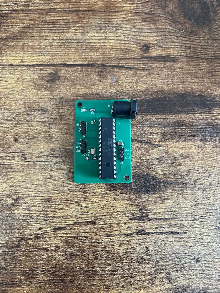 The PCB after soldering the components onto the board
Desinging the Enclosure
From my brainstorming sessions, I had a general idea of how the device should look. The two main requirements were that it would need a hole for the PIR sensor to peek out of, as well as an anchor point for the servo. Since the hand was the main focus of the device, I figured that insetting the servo in the body of the device would be the best option, so that it could be as flush and inconspicuous as possible. And since the PIR sensor would need to be unobstructed so as to have the largest peripheral vision, I determined it should go right below the hand in the center of the body.
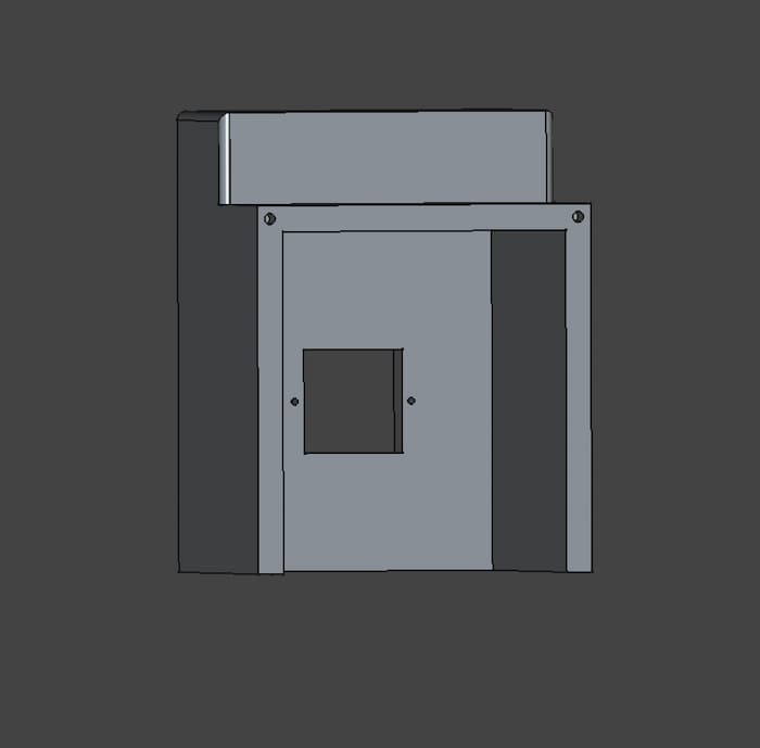
 The front view of the physical enclosure, designed in FreeCAD
 The base of the physical enclosure
 The back view of the physical enclosure
While fiddling with the CAD design, I also began to realize that I would need to print the body in two parts in order to affix everything inside while also keeping it enclosed.
So my final design included a base with mounting holes for the PCB, and the main body which included the front faces and insets for the PIR sensor and servo motor. After installing the PCB, sensor and servo, and connecting the wires to the pin headers, I could just enclose the two pieces and screw everything together.
Future Improvements
-
The PIR sensor is a bit reactive; since it detects any kind of motion, it triggers when people are just waiting by the elevator to leave. I think the optimal solution would involve image recognition, so that the hand only waves when you wave to it first. If the device had a camera, it could take a sample of photos for a period of time after detecting motion, and trigger when it determined that the person was waving (probably by just detecting an open palm).
-
I used screws to affix the baseplate and front body of the enclosure. I think a better solution would be a click-insert, or some mechanism to slide the pieces into place, like the battery compartment of a TV remote. PLA is brittle, and since the screw holes are a bit too close to the outside edge, it's liable to crack.
Conclusion
I'm excited to keep building my electronics, embedded, and mechanical skills. There's something so satisfying about building across these different engineering domains, and watching it all come together. Designing schematics, soldering, 3D printing, and programming firmware is a lot of fun, and I'm looking forward to sharing more of my designs.
References
Overview of Adafruit PIR Motion Sensor
What is a PWM Signal?
ATMEGA328-PU Datasheet
How to Solder SMD Components